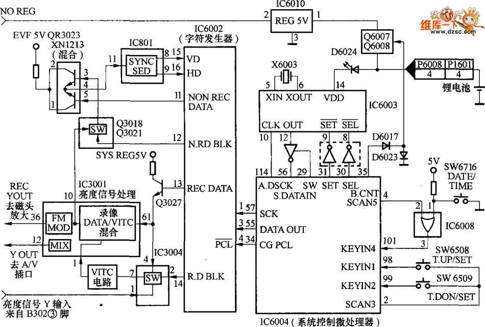
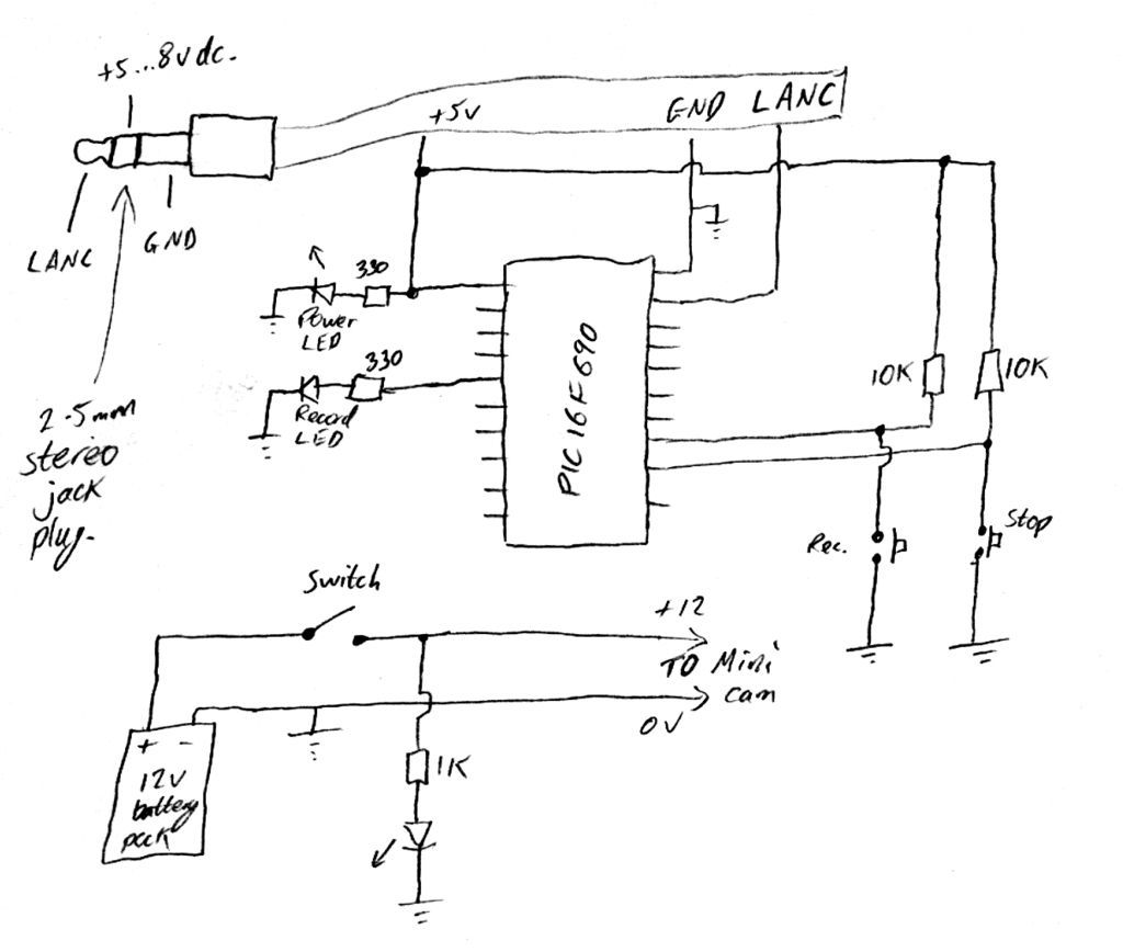
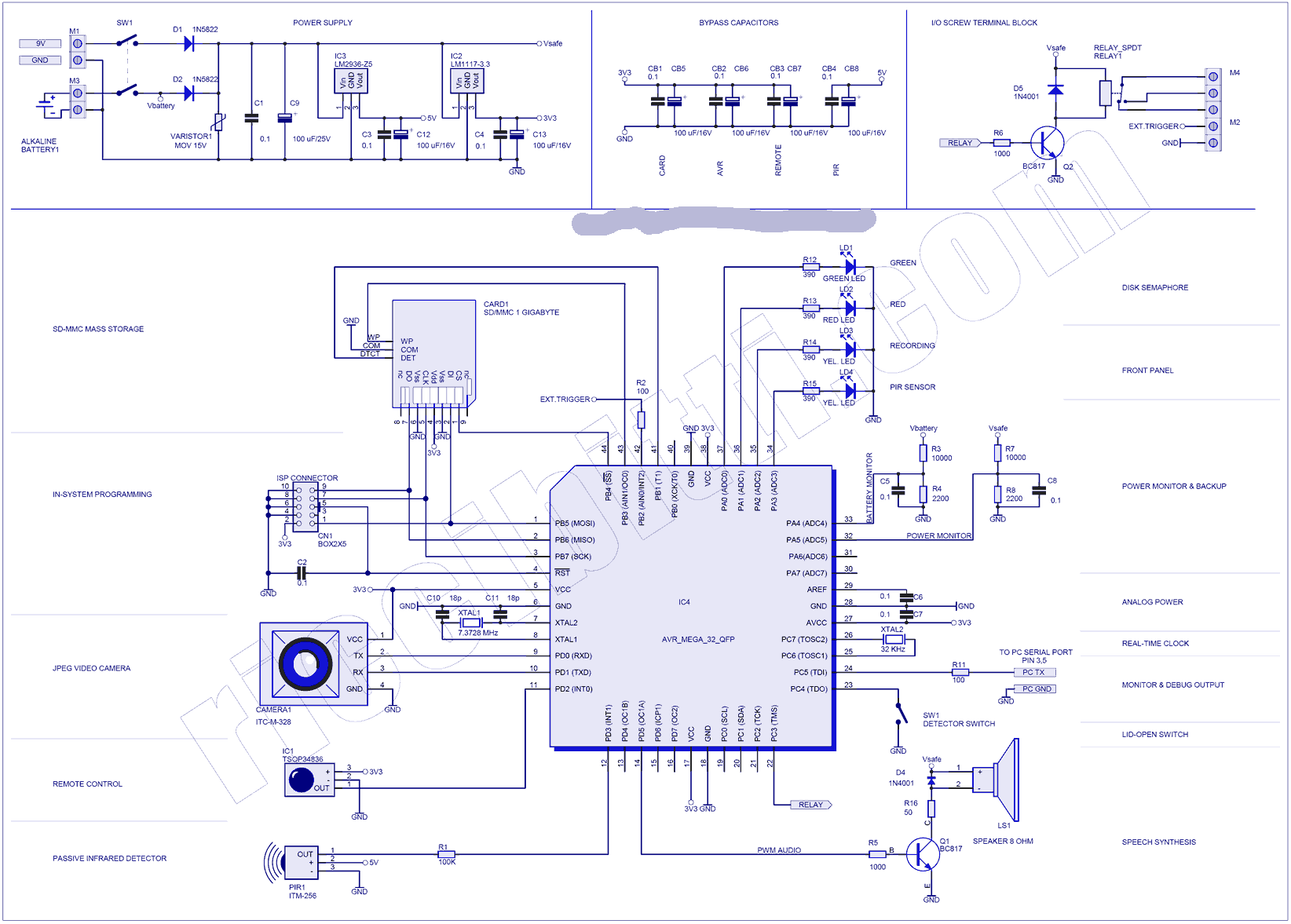
Cctv diagram should include the scheme of strategic placement of video cameras which capture and transmit videos to either a private network of monitors for real time viewing or to a video.
Cc camera jammer circuit diagram.
The cctv diagram provides video cameras placement strategy.
The gsm1900 mobile phone network is used by usa canada and most of the countries in south america.
Our mission is to put the power of computing and digital making into the hands of people all over the world.
The circuit can be made suitable with any desired frequency to be jammed by merely using different sets of l1 l2 and by tweaking the 22pf trimmers accordingly.
For any jammer circuit remember that there are three main important circuits.
Among the threats it can prevent you will find cctv cameras watching you every day on the streets of the city you live in rfid chips which are placed into more and more devices these days nfc technology that is embedded not only in many of our smartphones.
We do this so that more people are able to harness the power of computing and digital technologies for work to solve problems that matter to them and to express themselves creatively.
Gsm jammer or cell phone jammer is a device that transmit signal on the same frequency at which the gsm system operates the jamsming success when the mobile phones in the area where the jammer is located are disabled.
If you understand the above circuit this circuit analysis is simple and easy.
Uv30 is a uhf vhf jammer that is used as the desktop solution for protection against low frequencies and wireless threats related to them.
264 compression mode 8.
This cell phone jammer is not applicable for use in europe middle east nor asia.
Cell phone jammer circuit explanation.
Robot cctv camera wifi camera jammer wireless ip webcam toy camera for home alarm security main features 1 1 3 inch low lux cmos digital image sensor 2 960p 1280 960p pixels 1 3mp hd 3 3 6mm fixed lens 4 wireless wifi802 11b g n one key setup 5 wifi antenna built in the robot arms 6 with rj45 port also support wired ethernet cable 7 dual stream encoding h.
Simple mobile jammer circuit diagram.
Simple mobile jammer circuit diagram.
Description circuit showing a mobile phone jammer here i have used a fm transistor for making this circuit mobile phones are working in 450 mhz frequency here the transmitter generate almost equal to 450 mhz frequency there for the mobile phone does not identify the original signal but the signal range is very week so this circuit working in only 100 m range this circuit working in only 450.
Cctv closed circuit television diagram is used to depict a system of video monitoring.
When they are combined together the output of that circuit.
A simple looking rf signal jammer circuit can be seen in the above diagram which may be capable of jamming all sorts rf signal within the range of 5 to 10 meters.


